Arqlius One — the frozen pilot configuration
A 70-metre shared orbital hub in low Earth orbit: three service cores, a spoke-rooted adapter, three tenant rows with twelve identical berths, and a twelve-module cargo ring — laid out so that bulk propellant and dirty operations always stay two full segments from any tenant berth. Growth is by replication of this proven unit, not extension of the hull.
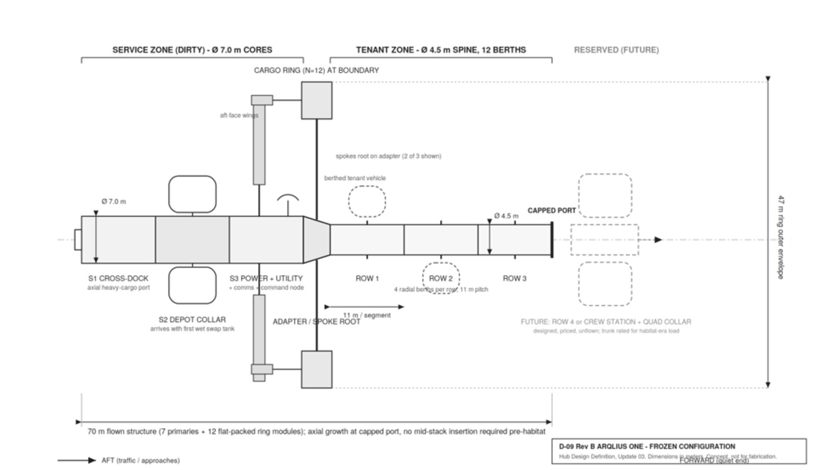
Three 7-metre cores carry everything hazardous, upstream of the tenants.
The service zone holds power, propellant and heavy cargo handling — physically separated from the tenant rows by the adapter boundary.
Cross-Dock
Axial heavy-cargo port and pallet cross-dock — the facility's front loading dock, where cargo transfers between vehicles without EVA.
Depot Collar
Radial swap-tank berths; arrives with the first storable tank wet and pressurants charged. Bulk propellant lives here, far from any tenant.
Power · Utility · Command
Tracked solar arrays, batteries, thermal trunk head-end, comms, guidance, and the Vexidus coordination node that schedules and settles every operation.
The adapter / spoke root tapers 7.0 m → 4.5 m and roots the three ring spokes on the stoutest structure of the spine. It is the service / tenant boundary — the line hazard does not cross.
Twelve identical berths. One rulebook.
Three tenant rows (R1–R3) present twelve identical 4.5 m × 11 m berths on an 11-metre pitch. Every berth is the same, so a tenant qualifies once and can fly to any port — and each berth is fault-isolated at its own service vault, so a fault in one tenant's system sheds only that berth.
An anchor tenant can start with a single isolated berth and scale to an entire row. Beyond the twelve, growth is replication — each new hull a discrete, financeable asset.

A twelve-module ring — ~1,300 m³ of leasable, robot-served storage.
A flat-packed N=12 ring deploys at the service / tenant boundary plane, adding roughly 1,300 cubic metres of net leasable volume served by robotics — no EVA required. Because the ring sits at the boundary, the rim-to-cross-dock cargo path is short, while bulk propellant stays two full segments away from any tenant berth.
Neutrality, expressed as geometry: hazard is kept upstream by design, not by policy.
Every berth is a fully serviced address.
Baseline interface provisions at each occupied berth. Values are preliminary and controlled through the Tenant Interface Control Document.
| Electrical power | 1 kW keep-alive to 15 kW peak per berth at 120 VDC, on independent dual A/B feeds, metered per port. Every kilowatt-hour is a settled custody event. |
|---|---|
| Thermal | Up to 5 kW heat rejection per berth via a single-phase coolant loop with self-sealing quick-disconnect couplings. |
| Data | Isolated tenant fibre channel, 1 Gb/s class sustained, relay-backhauled — physically and cryptographically isolated from every other tenant. |
| Propellant (future phase) | Storable fuel, oxidiser, pressurant and water at qualifying berths; activated by swap tank when a tenant contract creates the demand. |
| Cargo handling | Robotic cross-dock transfer between berths and to the ring — EVA-free by design. |
Published corridors, passively safe trajectories, one abort authority.
| Docking interface | IDSS-conformant, low-impact soft-capture class. Visiting vehicles carry the active counterpart; berth modules mate to the reserved-port loads envelope. |
|---|---|
| Vehicle mass | Visiting vehicle up to 12,000 kg at capture; resident berth module up to 5,000 kg attach mass. |
| Approach | Every approach enters a published 2,000 m arrival hold, then a per-berth corridor via ~400 m and ~30 m waypoints. Corridors never intersect and are auditable by all tenants. |
| Passive safety | Any loss of thrust on approach yields a trajectory that does not intersect the keep-out sphere — the hub holds unilateral abort authority inside it. |
| Reference orbit | Circular 440 km, 28.5° inclination (traffic-informed baseline), with a relocation capability held as a design requirement. |
A capped forward port, allocated by demand.
The forward tip of the third row is capped with full trunk capacity and habitat-era channel rating behind it. Because the tip is free, axial growth berths at the tip with no mid-stack insertion.
Row 4 or a crewed safe-haven module — the port is market-allocated, decided by demand rather than by the drawing.
- 70 mFlown structure — six spine flights plus three ring flights.
- 12Berths across three rows, plus twelve ring holds.
- ~1,300 m³Leasable ring volume, robot-served.
- +1Reserved port for a fourth row or crew module.
Configuration and interface values on this page are preliminary and pre-PDR, published early so tenant engineers can begin conforming their vehicles. They are controlled through the Tenant Interface Control Document and subject to change.